


Heavy duty trucks choose different types of transmission shafts based on the different driving forms of the loader transmission shaft structure. Generally speaking, cars with a 4x2 drive system only have one main drive shaft. A car with a 6 × 4 drive system has a middle drive shaft, a main drive shaft, and middle and rear axle drive shafts. A car with a 6 × 6 drive system not only has a middle transmission shaft, a main transmission shaft, and middle and rear axle transmission shafts, but also a front axle drive transmission shaft. The middle transmission shaft of a long wheelbase vehicle is generally equipped with a transmission shaft middle support, which is composed of a support frame, bearings, and rubber supports.
The transmission shaft is composed of a shaft tube, a telescopic sleeve, and a universal joint. The telescopic sleeve can automatically adjust the distance between the transmission and the drive axle. The universal joint ensures the variation of the angle between the output shaft of the transmission and the input shaft of the drive axle, and achieves equal angular velocity transmission between the two shafts. It is generally composed of universal joints, cross shafts, cross bearings, and flange forks. The transmission shaft universal joint used in the Steyr series heavy-duty vehicles adopts roller cross shaft bearings, coupled with short and thick cross shafts, which can transmit large torque. A butterfly spring is installed on the bearing end face to compress the rollers. The end face of the cross shaft is equipped with reinforced nylon gaskets with spiral grooves, which can prevent sintering when transmitting power at large angles or large turning distances.
The traditional structure of the transmission shaft expansion sleeve is to weld the spline sleeve and the flange fork together, and weld the spline shaft to the transmission shaft tube. GWB's transmission shaft has changed its traditional structure by welding the spline sleeve and transmission shaft tube together, and integrating the spline shaft with the flange fork. And change the rectangular tooth spline to a high pressure angle involute short tooth spline, which not only increases strength but also facilitates extrusion forming, adapting to the needs of high torque working conditions. On the surface of the teeth of the expansion sleeve and spline shaft, a layer of nylon material is applied as a whole, which not only increases wear resistance and self-lubricating properties, but also reduces the damage of impact load to the transmission shaft and improves the buffering capacity.
This type of transmission shaft is equipped with a tubular sealing protective sleeve outside the flange spline shaft, and two polyurethane rubber oil seals are installed at the end of the protective sleeve to create a completely sealed space inside the expansion sleeve, preventing the expansion spline shaft from being eroded by external dust and preventing dust and rust. Therefore, applying lubricating grease to the spline shaft and sleeve at once during assembly can fully meet the usage requirements, without the need for oil nozzle lubrication, reducing maintenance content.
The transmission shaft is a high-speed, low support rotating body, so its dynamic balance is crucial. Generally, the transmission shaft needs to undergo a dynamic balancing test before leaving the factory and be adjusted on the balancing machine. Therefore, a set of transmission shafts is factory matched, and special attention should be paid during use.
2. Interpretation of usage
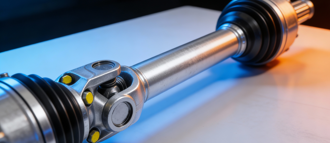
The transmission shaft assembly consists of an outer universal joint (RF joint), an inner universal joint (VL joint), and a spline shaft. Both the RF joint and VL joint are ball cage type constant velocity universal joints. The VL joint is connected to the differential drive shaft flange with bolts, and the RF joint is connected to the front wheel through a spline shaft at the outer wheel end. The left and right front wheels are driven by a constant velocity universal joint drive shaft.
1、 Disassembly and assembly of transmission shaft (half shaft) assembly: Disassembly of transmission shaft (half shaft) assembly.
(1) Dismantling
(1) When the wheels are on the ground, unscrew the fastening nuts between the drive shaft and the wheel hub.
(2) Unscrew the fastening bolts on the flange of the drive shaft.
(3) Separate the drive shaft from the flange.
(4) Pull out the drive shaft from the wheel bearing housing; Alternatively, use the pressure device V.A.G1389 to pull out the drive shaft.
Attention: When disassembling the transmission shaft, the wheel hub must not be heated, otherwise it will damage the wheel bearings. In principle, a puller should be used. After removing the transmission shaft, a connecting shaft should be installed to replace the transmission shaft to prevent damage to the front wheel bearing assembly when moving the vehicle with the transmission shaft removed.
(2) Installation
(1) Clean the oil stains on the transmission shaft and splines, and apply lithium based grease.
(2) Apply a circle of 5mm protective agent D6 on the splines of the external universal joint (RF joint), and then install the drive shaft spline sleeve. The transmission shaft coated with protective agent should be parked for 60 minutes after installation before the car can be used.
(3) Reinstall the ball joint pin in its original position and tighten the nut. When installing the ball joint pin, do not damage the bellows sleeve.
(4) Check the front wheel camber angle if necessary.
(5) After the wheels land, tighten the wheel hub fixing nut.
2、 Dismantling of universal joints
(1) Use a steel saw to cut open the clamp on the universal joint dust cover and remove the dust cover.
(2) Use a light metal hammer to forcefully knock off the outer universal joint (RF joint) from the drive shaft.
(3) Remove the spring lock ring.
(4) Press out the inner universal joint (VL joint).
(5) Before dismantling, mark the position of the inner star wheel on the steel ball cage and outer planet wheel with an electric erosion pen or oilstone.
3、 Disassembly of universal joints
(1) External universal joint (RF joint)
(1) Rotate the inner star wheel and ball cage, and sequentially remove the steel balls.
(2) Rotate the steel ball cage vigorously until the two square holes are aligned with the alien wheel, and remove the cage together with the alien wheel.
(3) Rotate the fan-shaped teeth on the inner star wheel into the square hole of the cage, and then remove the inner star wheel from the cage.
(2) Internal universal joint (VL joint)
(1) Rotate the inner star wheel and cage to press out the steel balls inside the cage. Attention: The inner star wheel and the housing are optional and cannot be interchanged.
(2) Remove the inner star wheel from the ball cage above the groove.
(3) Inspection of components
(1) Check for dents and wear on the outer planet wheel, inner planet wheel, ball cage, and steel ball.
(2) The 6 steel balls at each universal joint require a certain fitting tolerance and form a set of fitting parts together with the inner star wheel.
(3) If the clearance between the universal joints is significantly too large, the universal joints must be replaced. If the universal joint is smooth and undamaged or if the steel ball can be seen running, there is no need to replace the universal joint.
(4) Check if the dust cover is broken and if the retaining ring and seat ring are malfunctioning, otherwise they should be replaced.
4、 Assembly of universal joints
RCD-30 transmission shaft balancing machine (I) internal universal joint (VL joint)
(1) Align the groove and insert the inner star wheel into the cage, the position of the inner star wheel inside the cage is irrelevant.
(2) Press the steel ball into the cage and inject 90g of G6 grease.
(3) Insert the alien wheel with steel ball and cage vertically into the shell. Attention: After rotation, the wide gap a on the outer planet wheel should align with the narrow gap b on the inner planet wheel, and rotate the cage to fit in place; The chamfer on the inner diameter (key teeth) of the inner star wheel must be aligned with the large-diameter end of the outer star wheel.
(4) Twist the inner star wheel so that it can rotate out of the cage and provide enough clearance for the steel ball to match the groove in the outer star wheel.
(5) Use force to pull and press the ball cage, causing the inner star wheel containing the steel ball to completely turn into the outer star wheel.
(6) Push the inner star wheel back and forth within the axial range by hand. If it is flexible, it indicates correct assembly.
(2) External universal joint
(1) Clean all components with gasoline.
(2) Inject half of the total amount of G6 grease (45g) into the universal joint.
(3) Install the ball cage together with the inner star wheel into the outer planet wheel.
(4) Press the steel ball diagonally alternately, and keep the inner star wheel in its original position inside the cage and the outer star wheel.
(5) Install the spring lock ring into the inner star wheel.
(6) Press the remaining grease into the universal joint.
(7) Push the inner star wheel back and forth within the axial range by hand to check if the installation is correct.
5、 Installation of internal and external universal joints
(1) Install a protective cover on the drive shaft.
(2) Correctly install the disc-shaped seat ring.
(3) Press the inner universal joint into the drive shaft. Make the disc-shaped seat ring fit tightly, and the chamfer on the inner diameter of the star wheel (keyway) must face the shoulder of the transmission shaft.
(4) Install the spring lock ring.
(5) Install the external universal joint.
(6) When installing a dust cover on a universal joint, the dust cover often needs to be compressed. Therefore, a certain vacuum is generated inside the dust cover, which will create an inward suction crease during vehicle operation. Therefore, after installing the small diameter dust cover, it is necessary to slightly inflate it to balance the pressure and prevent wrinkles.
(7) Clamp the dust cover with a clamp. The new pliers model used is V.A.G1275.
3. Drive shaft balance
The dynamic balance of the transmission shaft has the following six functions:
1. Improve the quality of rotors and their components;
2. Reduce noise;
3. Reduce vibration;
4. Improve the service life of supporting components (bearings);
5. Reduce user discomfort;
6. Reduce the power consumption of the product.
4. Common faults
The damage, wear, deformation, and loss of dynamic balance of the transmission shaft components of Fukang sedan can cause abnormal noise and vibration during driving, and in severe cases, damage to related components. When a car is driving, it makes a "Geden" sound when starting or accelerating rapidly, and clearly shows a feeling of loose parts. If it is not a loose drive axle transmission gear, it is obviously a loose transmission shaft part. The loose parts are mainly universal joint cross bearings or steel bowls and flange forks, as well as the spline shaft and spline sleeve of the expansion sleeve. Generally speaking, the diameter of the cross shaft and the clearance of the bearing should not exceed 0.13mm, and the clearance between the expansion spline shaft and the spline sleeve should not exceed 0.3mm. If it exceeds the limit of use, it should be repaired or replaced.
If the chassis makes a buzzing sound while driving, and the higher the speed, the louder the sound. This is usually due to wear and looseness of the universal joint cross shaft and bearings, wear of the middle bearing of the transmission shaft, damage to the middle rubber support or looseness of the hanger, or due to incorrect fixing position of the hanger.
When a 6 × 4 car is under heavy load, especially during bumpy driving, occasional knocking sounds should be made. Attention should be paid to checking whether the balance shaft of the middle and rear axles has shifted and interfered with the transmission shaft. If the noise and vibration increase with the increase of vehicle speed during operation, it is generally due to the imbalance of the transmission shaft. This vibration is most noticeable in the driver's cabin. The unbalance of the dynamic balance of the transmission shaft should be less than 100g. cm
Severe failure of the dynamic balance of the transmission shaft can lead to damage to related components. The most common are cracks in the clutch housing and fatigue damage to the middle rubber support.
The installation of the suspension bracket in the middle of the transmission shaft is very important during maintenance. If the installation position of the hanger is improper, it will increase the running resistance and noise of the transmission shaft, leading to early damage of the bearings. When reinstalling the hanger, first do not tighten the fixing bolts of the hanger. Use a jack to lift the car drive wheel off the ground, shift to low gear, slowly rotate the transmission shaft to automatically align with the hanger, and then tighten the fixing bolts of the hanger.
5. Usage and maintenance
To ensure the normal operation of the transmission shaft and extend its service life, attention should be paid to the following during use:
1. It is strictly prohibited to start a car in high gear.
2. Do not forcefully lift the clutch pedal.
3. Overloading and speeding of vehicles are strictly prohibited.
4. The working condition of the transmission shaft should be checked regularly.
5. Regularly check the fastening of the transmission shaft hanger, whether the supporting rubber is damaged, whether the connection parts of the transmission shaft are loose, and whether the transmission shaft is deformed.
6. Lubricating grease should be regularly added to the universal joint cross bearing. In summer, No. 3 lithium based grease should be injected, and in winter, No. 2 lithium based grease should be injected. 7. In order to ensure the dynamic balance of the transmission shaft, it is necessary to regularly pay attention to whether the balance welding plate is detached. The new transmission shaft component is provided as a complete set. When installing the new transmission shaft, attention should be paid to the assembly markings of the expansion sleeve, and the flange fork should be ensured to be in the same plane. When repairing and disassembling the transmission shaft, assembly marks should be printed on the expansion sleeve and flange shaft to maintain the original assembly relationship during reassembly.
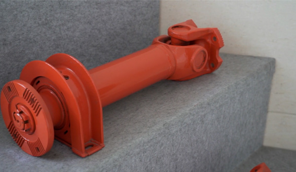
6. Structure and working environment
The transmission shaft assembly mainly consists of a transmission shaft and its two end welded spline shafts and universal joint forks. A sliding spline composed of a sliding fork and a spline shaft is generally installed in the transmission shaft to achieve changes in transmission length. In order to reduce the axial sliding resistance and wear of sliding splines, sometimes phosphating treatment or nylon coating is applied to the spline teeth; Some of them insert rolling elements such as needles, rollers, or balls into the spline groove to replace sliding friction with rolling friction and improve transmission efficiency. But this structure is more complex and costly. Sometimes, for transmission with severe impact loads, elastic transmission shafts are also used. The splines on the transmission shaft should have lubrication and dust prevention measures. The clearance between the spline teeth and the keyway should not be too large, and should be assembled according to the corresponding markings to avoid incorrect installation and damage to the dynamic balance of the transmission shaft assembly.
The length and angle of the transmission shaft, as well as their range of variation, are determined by the overall layout design of the vehicle. When designing, it should be ensured that there is sufficient fit length between the spline sleeve and the shaft when the transmission shaft length is at its maximum value; And when the length is at its minimum, it does not collapse. The size of the transmission shaft angle directly affects the service life of the universal joint cross shaft and needle roller bearing, the efficiency of universal transmission, and the unevenness of the cross shaft rotation.
Couplings are used in conjunction with various host products, and the surrounding working environment is relatively complex, such as temperature, humidity, water, steam, dust, sand, oil, acid, alkali, corrosive media, salt water, radiation, etc., which are important factors that must be considered when selecting couplings. For the working quality of high temperature, low temperature, oily, acidic, and alkaline media, it is not advisable to use flexible couplings with general rubber as the elastic element material. Instead, metal elastic element flexible couplings such as diaphragm couplings, serpentine spring couplings, etc. should be selected.
Henan Tongxin Transmission Co., Ltd., founded in 2001, is located in the Economic and Technological Development Zone of Xuchang City, Henan Province, covering an area of 80000 square meters. It is a national "specialized, refined, unique, and new" small giant enterprise and a national high-tech enterprise. And officially listed on the Beijing Stock Exchange on November 15, 2021.
The company has its own 'technology center', dedicated to improving product quality and constantly innovating technical processes. With over 40 patented properties, we have pioneered the forging of blank raw materials with "hollow cores and no waste edges" in the industry, and our technology has reached the international priority level. The company relies on advanced production technology, sophisticated equipment, efficient production organization capabilities, strict quality control system, and excellent full-service model; With the quality policy of "pursuing zero defects and satisfying customers", we aim to build our enterprise into a specialized transmission shaft service platform. Adhering to the business philosophy of "seeking profits from products, not from customers", we aim to achieve win-win cooperation with our customers.
 Tel: +86-18838478091
 Email: Joe@hntxcd.com
 Add: South of Changqing Street, Economic and Technological Development Zone, Xuchang City, Henan Province