


Integrated drive shafts are used to connect or assemble various components. Light-alloy steel tubes with high torsional resistance are generally adopted for rotating or reciprocating circular attachments.
In vehicles with a front engine and rear-wheel drive, the integrated drive shaft transmits rotation from the transmission to the final drive axle. It may consist of multiple universal joints connected in series. As a high-speed, lightly-supported rotating body, its dynamic balance is critically important. Normally, integrated drive shafts must undergo a dynamic balance test before delivery and be adjusted on a balancing machine.
Functions
The integrated drive shaft is a key component in the automotive transmission system for power transmission. Its role is to transfer engine power—together with the transmission and drive axle—to the wheels, generating driving force for the vehicle.
Applications
Integrated drive shafts for special vehicles are mainly used in:
tank trucks, refueling trucks, sprinklers, sewage suction trucks, fecal suction trucks, fire engines, high-pressure cleaning trucks, road wreckers, aerial work platforms, and other special vehicles.
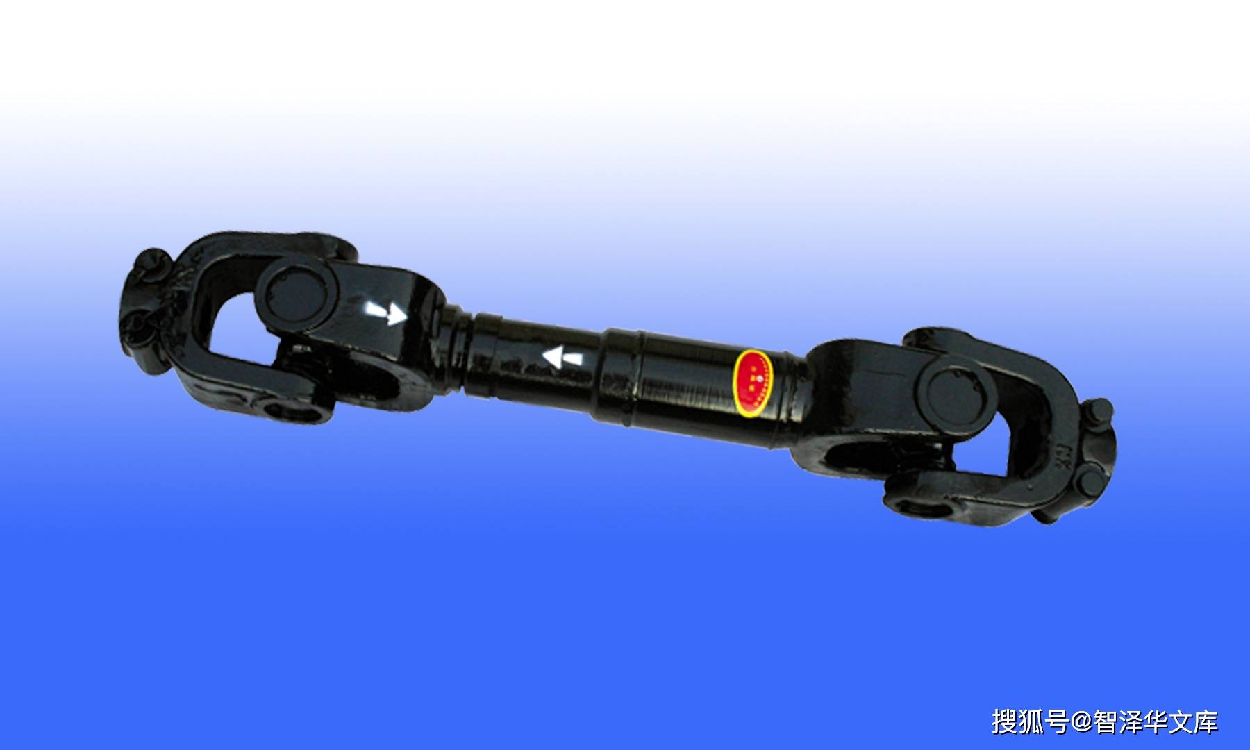
Structure
The integrated drive shaft consists of a shaft tube, a sliding sleeve, and universal joints.
The sliding sleeve automatically compensates for changes in distance between the transmission and the drive axle.
The universal joint accommodates angular variations between the transmission output shaft and the drive axle input shaft, enabling constant-velocity power transmission between the two shafts.
Universal Joint
The universal joint is a critical component of the automotive integrated drive shaft.
A vehicle is a moving assembly. In rear-wheel-drive vehicles, the engine, clutch, and transmission are mounted as a unit on the chassis frame, while the drive axle is connected to the frame via elastic suspension. A distance exists between them that must be connected. During operation, road irregularities cause vertical movement and bouncing.
1. Function
A typical universal joint consists of a cross shaft, cross bearings, and flange yokes.
In front-engine, rear-wheel-drive vehicles, the universal joint drive shaft is installed between the transmission output shaft and the input shaft of the drive axle final drive.
In front-engine, front-wheel-drive vehicles, the integrated drive shaft is eliminated; universal joints are mounted between the front axle half-shafts and the wheels, providing both drive and steering functions.
During vehicle operation, uneven road surfaces cause bouncing, load changes, or differences in mounting positions, which alter the angle and distance between the transmission output shaft and the drive axle input shaft. A “variable-length” device is required to resolve this issue, hence the universal joint.
2. Transmission Characteristics
In front-engine, rear-wheel-drive (or all-wheel-drive) vehicles, relative movement typically occurs between the drive shaft, final drive input shaft, and transmission (or transfer case) output shaft due to suspension deformation during travel.
Additionally, to avoid mechanical interference that would prevent straight-line transmission, a device is needed to ensure normal power transmission—this is achieved by universal joint drive.
Universal joint drive must meet the following requirements:
a. Ensure reliable power transmission when the relative position of the two connected shafts varies within the expected range.
b. Ensure uniform rotation of the two connected shafts. Additional loads, vibration, and noise caused by the universal joint angle must be within acceptable limits.
 Tel: +86-18838478091
 Email: Joe@hntxcd.com
 Add: South of Changqing Street, Economic and Technological Development Zone, Xuchang City, Henan Province